


Alimentation de charge haute tension robuste et haute puissance
Obtenir le dernier prix| Type de paiement: | T/T |
| Incoterm: | FOB,CFR,CIF,EXW |
| Quantité de commande minimum: | 1 Piece/Pieces |
| transport: | Ocean,Land,Air,Express |
| Hafen: | SHANGHAI,NANJING,QINGDAO |

| Type de paiement: | T/T |
| Incoterm: | FOB,CFR,CIF,EXW |
| Quantité de commande minimum: | 1 Piece/Pieces |
| transport: | Ocean,Land,Air,Express |
| Hafen: | SHANGHAI,NANJING,QINGDAO |
Modèle: CCPS
marque: IDEALTEKNIC
Lieu D'origine: Chine
Puissance De Sortie: > 500 W
Le Type De Sortie: Seul
Input Voltage: Three Phase 380vac
Input Frequency: 50/60hz
Working Principle: Pwm
Power Supply Type: Igbt-Based
Working Mode: Constant Voltage / Constant Current
Display Mode: Lcd
Control Mode: 10-Turn Potentiometers
Protections: Input Lack Phase, Ovp, Ocp, Otp, Short-Circuit Protections Etc., Ocp, Short Circuit And Load Dischargin
Applications: Capacitor Charging, Electrostatic Precipitator, Semiconductor Process, Lab Test / Hipot / Capacitor Charging
Cooling: Forced Air Cooling
Circuit Mode: Pwm
Output Voltage Range: 5 Kv ~ 60 Kv
Output Current Range: 100 Ma ~ 2400 Ma
| Unités de vente | : | Piece/Pieces |
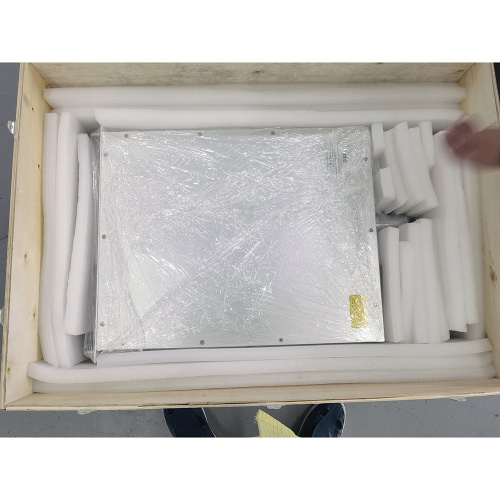
| Type de colis | : | Caisse en contreplaqué |
| Exemple d’image | : |
|
| Télécharger | : |
|

Alimentation CC de charge de condensateur haute tension série CCPS
Aperçu
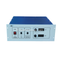
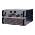
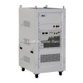
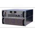
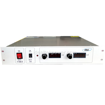
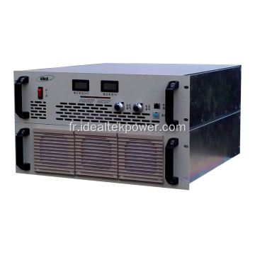
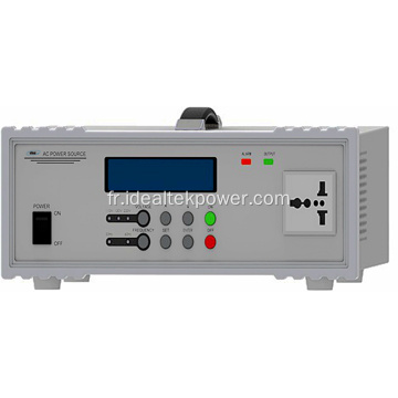
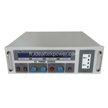
L'alimentation haute tension de la série CCPS-6U est une version améliorée des alimentations de charge de condensateur haute tension CCP-6U. Il utilise un châssis monté en rack standard de 19 pouces 6U, avec une puissance de sortie allant jusqu'à 10KW et un niveau de tension de sortie de 5KV / 10KV / 20KV / 30KV / 40KV / 50KV / 60KV, les alimentations de charge haute tension ont atteint une augmentation substantielle de la capacité de charge des alimentations de charge de condensateur HT montées en rack sur la base du maintien d'un rendement élevé, d'une vitesse de réponse de sortie élevée et d'une protection plus rapide et d'un démarrage automatique.
Le panneau avant de cette série d'alimentations haute tension de charge de condensateur est contrôlé par un potentiomètre avec les compteurs LCD indiquant la sortie haute tension. Cette série de condensateurs de charge HVPS peut être équipée d'une interface RS485 et d'un logiciel de contrôle pour contrôler et surveiller les paramètres de fonctionnement du condensateur de charge HVPS.
L'alimentation est équipée de protections plus complètes pour assurer un fonctionnement à long terme et fiable du chargeur de condensateur HT à pleine charge, telles que: perte de phase d'entrée, surtension de sortie, surintensité, surchauffe, protection contre les courts-circuits, etc., et peut être également équipé d'un circuit de décharge pour gérer les conditions de charge et de décharge haute tension pour une protection efficace des alimentations haute tension et des condensateurs testés.

Caractéristiques
je Peut être utilisé comme alimentation CC HV ou comme alimentation de charge de condensateur HV.
je Tension de sortie réglable de 0 à 100%
je Puissance de sortie : charge moyenne à 5 KJ/S et la puissance de charge maximale peut atteindre 12 KW.
je Chargez en mode courant constant et passez en mode courant constant jusqu'à ce qu'il soit complètement chargé.
je Système unique à double isolation, forte capacité anti-interférence.
je Refroidissement par air forcé, conception très robuste.
Applications
Charge de condensateur, précipitateur électrostatique, procédé semi-conducteur.
Précautions de sécurité
1. Ce module d'alimentation a une sortie HV, seule une personne professionnelle peut l'utiliser.
2. Veuillez vous assurer d'une bonne mise à la terre avant l'utilisation.
3. L'alimentation de charge du condensateur a une faible énergie stockée en interne, veuillez ne pas fonctionner sans charge.
4. Gardez le module d'alimentation propre et une bonne ventilation.
5. Les connecteurs d'entrée et de sortie HV ou la charge HV ne touchent rien.
|
Input |
Connection mode |
Three-phase, four-wire (PE), TN-S supply mode |
|
|
Voltage |
380Vac±10% |
||
|
Frequency |
50Hz/ 60Hz ± 10% |
||
|
Current |
As per output power. |
||
|
Output |
Rated power |
6KW ~ 12KW (Max.) available ** |
|
|
Output voltage adjusting range |
5KV ~ 60KV available ** (For other output voltages, please contact us for details) |
||
|
Output current adjusting range |
0A ~ ****mA |
||
|
Output polarity |
Positive or Negative (both available) Client must choose one output polarity before ordering. |
||
|
Working mode |
Constant voltage (CV) / Constant current (CC) |
||
|
Accuracy (C.V.) |
Line regulation |
≤0.5% FS ± 1 digit (Output voltage change rate only caused by changes of input voltage over ± 10% range of variation) |
|
|
Load regulation |
≤1% FS ± 1 digit (Output voltage change rate only caused by full range load changes) |
||
|
Accuracy (C.C.) |
Line regulation |
≤0.5% FS ± 1 digit (Output voltage change rate only caused by changes of input voltage over ± 10% range of variation) |
|
|
Load regulation |
≤0.5% FS ± 1 digit (Output voltage change rate only caused by full range load changes) |
||
|
Temperature drift |
≤0.03% FS (Output voltage change rate every 8 hours after power on for half an hour) |
||
|
Ripple (p-p) |
≤0.5% FS (measured @ 80% ~ 100% rated output) |
||
|
Output cable |
HV connector and line provided by IdealTek. |
||
|
Efficiency |
≥90% |
||
|
Setting & Display |
Control mode |
Local |
10-turn potentiometer on front panel. |
|
Remote (Optional) |
RS485 communication interface. In line with MODBUS-RTU standard. The user can control and monitor the power supply via RS485 connection with computer, E.g: l Power ON / OFF l Output voltage & current setting & reading. l Working state monitoring (constant voltage, constant current, fault) |
||
|
Display mode |
41/2 LCD digital display |
||
|
Display error |
≤±0.5%FS ± 1digit (range: 5%~100% of the rated value) |
||
|
Display resolution |
As per output voltage & current values. |
||
|
Protection & Monitoring functions |
Input protection |
Input lack phase protection. |
|
|
Output over voltage protection (OVP) |
Power supply automatically cuts off output and alarms when output has over voltage. |
||
|
Output over current protection (OCP) |
Power supply automatically cuts off output and alarms when the output has over current. |
||
|
Over temperature protection (OTP) |
Power supply automatically cuts off output and alarms when the internal temperature of the power supply exceeds its threshold value. |
||
|
Output short-circuit protection |
Power supply automatically switches to CC working when the output has short-circuit. |
||
|
Over-loading capacity |
Withstand working with 1.05 times of rated current. |
||
|
Noise |
≤65dB |
||
|
Protection degree |
IP20 |
||
|
Cooling method |
l Forced air cooling l Forced air cooling + internal water-cooling loop. Direction: The lower part of the left and right sides - In and Top - Out wind. Differ as per output power rating. |
||
|
Inverter transient protection response time |
≤10us |
||
|
Working environment conditions |
Ambient temperature |
-5℃~+45℃ |
|
|
Humidity |
10%~80%(non-condensing) |
||
|
Height |
≤1000m |
||
|
Location |
Indoor use only No conductive dust, gas or steam that destroys the insulating medium No severe vibration and shock, good ventilation. |
||
|
Size (W*H*D) (mm) |
482*265.5*566.5 (19” 6U standard chassis) |
||
|
Weight |
Approx. 45Kg |
||
|
|
|||
|
Front panel description |
||||||||
 |
||||||||
|
No. |
Name |
Function |
Operation / display instruction |
|||||
|
F1 |
Control cabinet air inlet |
Control cabinet heat dissipation air inlet |
Keep it clean and smooth |
|||||
|
F2 |
Handle |
For moving and lifting purpose |
|
|||||
|
F3 |
Mounting hole |
For cabinet installing and fixing |
|
|||||
|
F4 |
POWER switch |
Supply electric ON/OFF switch |
Switch to ON position è Power ON Switch to OFF position è Power OFF |
|||||
|
F5 |
VOLTAGE |
Output voltage real-time display |
Digital LED display |
|||||
|
F6 |
CURRENT |
Output current real-time display |
Digital LED display |
|||||
|
F7 |
Indicator lights |
Real-time indication of module working state |
Indicator lights display |
|||||
|
F8 |
Voltage Adj. |
Output voltage adjusting |
Turn as icon, clockwise adjusting for increasing output voltage, anticlockwise adjusting for decreasing output voltage. |
|||||
|
F9 |
Current Adj. |
Output current adjusting |
Turn as icon, clockwise adjusting for increasing output current, anticlockwise adjusting for decreasing output current. |
|||||
|
F10 |
Analog port |
232/485 optional port (N/A for this unit) |
Please connect to DB9 port for communication with host. |
|||||
|
F11 |
Start/Stop (with lock) |
HV output start/stop |
Press down (green light ON) è HV START Press up (green light OFF) è HV STOP |
|||||
|
F12 |
Charging/Charged |
Charging / Charged state indicator light |
Charging lighted è Under charging. Charged lighted è Charging finished. |
|||||
|
Front Panel Indicator Lights Description |
||||||||
 |
||||||||
|
No. |
Name |
Function |
Operation / display instruction |
|||||
|
F13 |
Host indicator light |
Green LED light, lighted when power supply works as host unit under multi-unit parallel-working. Note: host indicator light lighted under single-unit working. |
Indicator lights display |
|||||
|
F14 |
Slave indicator light |
Green LED light, lighted when power supply works as slave unit under multi-unit parallel-working. Note: slave indicator light not lighted under single-unit working. |
Indicator lights display |
|||||
|
F15 |
C.V. indicator light |
Green LED light, lighted when power supply works under CV state. |
Indicator lights display |
|||||
|
F16 |
C.C. indicator light |
Green LED light, lighted when power supply works under CC state. |
Indicator lights display |
|||||
|
F17 |
Flashover indicator light |
Red LED light, lighted when power supply output has disruptive discharging. |
Indicator lights display |
|||||
|
F18 |
OC indicator light |
Red LED light, lighted when power supply has internal inverter output over current. |
Indicator lights display |
|||||
|
F19 |
Out short indicator light |
Red LED light, lighted when power supply has output short-circuits. |
Indicator lights display |
|||||
|
F20 |
OP indicator light |
Red LED light, lighted when output power of high voltage power supply exceeds the limit. |
Indicator lights display |
|||||
|
F21 |
Inhibit indicator light |
Red LED light, lighted when power output is prohibited by client's external nodes. |
Indicator lights display |
|||||
|
F22 |
OT indicator light |
Red LED light, lighted when power supply has internal module over temperature. |
Indicator lights display |
|||||
|
F23 |
Grid indicator light |
Red LED light, lighted when power supply has input abnormal (i.e.: lack phase or out of scope) |
Indicator lights display |
|||||
|
F24 |
IGBT indicator light |
Red LED light, lighted when power supply has internal inverter fault |
Indicator lights display |
|||||
|
F25 |
OV indicator light |
Red LED light, lighted when output voltage goes out of scope. |
Indicator lights display |
|||||
|
F26 |
Load OC indicator light |
Red LED light, lighted when output current goes out of scope. |
Indicator lights display |
|||||
|
F27 |
APS indicator light |
Red LED light, lighted when internal auxiliary power supply is working. |
Indicator lights display |
|||||
|
Back panel description |
||||||||
 |
||||||||
|
No. |
Name |
Function |
Operation / display instruction |
|||||
|
B1 |
GND |
Main circuit part, connected to earth. |
Separately connected to earth. |
|||||
|
B2 |
HV cabinet (Feedback) air socket |
For connection of HV cabinet and control cabinet. |
Connect to control cabinet (Feedback) air plug |
|||||
|
B3 |
Control cabinet (H-power) air socket |
For connection of control cabinet and HV cabinet. |
Connect to HV cabinet (H-power) air plug |
|||||
|
B4 |
Control cabinet input port |
Remote 485 signal input port |
Leave it unconnected if no 485 signal used. |
|||||
|
B5 |
Control cabinet DB9 port |
Remote control / reading port |
Connect in external analog signal for remote control / reading (i.e.: 0~10V) |
|||||
|
B6 |
Control cabinet DB15 port |
Remote start/stop, fault state TTL signal port |
Connect in external start/stop signal (i.e.: 24V) Connect in external analog signal for fault state indication (i.e.: TTL signal) |
|||||
|
B7 |
Control cabinet (Feedback) air socket |
For connection of control cabinet and HV cabinet |
Connect to HV cabinet (Feedback) air plug |
|||||
|
B8 |
Cooling fan (temperature-controlled) |
Exhaust fan, controlled by temperature inside the cabinet |
The higher the temperature inside cabinet, the faster the fan speed is. |
|||||
|
B9 |
IN 480V~600VDC |
Connects to DC480V~600V input |
Red is positive, black is negative. |
|||||
|
B10/11 |
HV-output |
Negative HV output connector |
Connection port |
|||||
|
B12 |
Power GND |
Positive output connector |
Connection port |
|||||
|
B13 |
HV cabinet (H-power) air socket |
For connection of HV cabinet and control cabinet. |
Connect to control cabinet (H-power) air plug |
|||||
|
Remote interface definition |
||||||||
|
|
||||||||
|
B4 Wiring diagram / B5 Internal wiring / B6 Wiring diagram |
||||||||
|
No. |
Name |
Function |
Operation / display instruction |
|||||
|
Z-1 |
485-A |
485-A |
485-A |
|||||
|
Z-2 |
485-B |
485-B |
485-B |
|||||
|
Z-3 |
Remote ON/OFF state node (optional) (N/A for this unit) |
ON/OFF state node + |
Power OFF, node closed Power ON, node open |
|||||
|
Z-4 |
|
ON/OFF state node - |
|
|||||
|
X1 |
Voltage remote control (optional) (N/A for this unit) |
Voltage remote control + |
0-10V signal for 0-15KV output voltage setting |
|||||
|
X2 |
|
Voltage remote control - |
|
|||||
|
X3 |
Current remote control (optional) (N/A for this unit) |
Current remote control + |
0-10V signal for 0-1000mA output current setting |
|||||
|
X4 |
||||||||
|
KV |
mA |
P (KW) |
Model |
KV |
mA |
P (KW) |
Model |
|
5 |
1200 |
6 |
CCPS-(N/P)6kW-5kV |
10 |
1200 |
12 |
CCPS-(N/P)12kW-10kV |
|
10 |
600 |
6 |
CCPS-(N/P)6kW-10kV |
15 |
800 |
12 |
CCPS-(N/P)12kW-15kV |
|
15 |
400 |
6 |
CCPS-(N/P)6kW-15kV |
20 |
600 |
12 |
CCPS-(N/P)12kW-20kV |
|
20 |
300 |
6 |
CCPS-(N/P)6kW-20kV |
30 |
200 |
6 |
CCPS-(N/P)6kW-30kV |
|
30 |
167 |
5 |
CCPS-(N/P)5kW-30kV |
40 |
150 |
6 |
CCPS-(N/P)6kW-40kV |
|
40 |
125 |
5 |
CCPS-(N/P)5kW-40kV |
45 |
133 |
6 |
CCPS-(N/P)6kW-45kV |
|
50 |
100 |
5 |
CCPS-(N/P)5kW-50kV |
50 |
120 |
6 |
CCPS-(N/P)6kW-50kV |
|
60 |
100 |
6 |
CCPS-(N/P)6kW-60kV |
60 |
200 |
12 |
CCPS-(N/P)12kW-80kV |
|
|
|||||||
l 0 ~ 10V Contrôle du signal analogique (interface DB) (+ AC)
l Interface de communication RS (RS232 / RS485 Facultatif) (+ RC)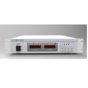


Privacy statement: Your privacy is very important to Us. Our company promises not to disclose your personal information to any external company with out your explicit permission.
Fill in more information so that we can get in touch with you faster
Privacy statement: Your privacy is very important to Us. Our company promises not to disclose your personal information to any external company with out your explicit permission.